Sunday, May 28, 2017

Making a (really simple) game to Learn rust.

So there was a a post on hacker news On making a game in Rust.    In the comments I mentioned it would be nice to have a simple game example to enable people to learn Rust by extending the example.

Rather than sit and hope that such an example turns up I thought I should have a go myself.   The problem with that is, of course, that I don't have a very good grasp on Rust myself.   I wanted the example to give myself a base to learn from.   Nevertheless I'm diving in and we'll see how it ends up.
Bored already? Just download the example and dive in. http://fingswotidun.com/blag/tinydraw_rust/tinydraw_rust.tar.gz

In the responses to my comment someone pointed me to  rust_minifb
which does look like a good place to start.

I got my ChromeBook with Crouton and ran rustup to get me up to date and made a tiny program using rust_minfb.   It didn't work.  A somewhat inauspicious start. 

My code, as little as there was of it, appeared to be fine.   The error was in building rust_minifb.  

"can't find crate x11_dl"  cargo wailed.

But wait! Here it is https://crates.io/crates/x11-dl

The detail in which the devil was concealing itself was the altitude of a single character.

rust_minifb wanted x11_dl
cargo had  x11-dl (note the dash instead of underscore

Had I found a bug in rust_minifb?  I asked on #rust-beginners.   A helpful resident tried


git clone https://github.com/emoon/rust_minifb
cd rust_minifb
cargo run --example noise

and reported that the noise example worked fine for them. 

I tried the same procedure on my ChromeBook and was rewarded with the familiar "can't find crate x11_dl"

At this stage I did what any reasonable person in this position would do.  I moved to my desktop machine.  cargo run --example noise worked, as did my tiny test program.  I could put pixels onscreen. Hooray
rust_minifb also gives us some input. The Window struct provides methods such as get_mouse_pos and is_key_down. We can read input and we can put something on screen, that's two of the main requirements for a game. We still need a sense of time. Turns out Rust makes this bit quite easy.

    let (ticker_tx,ticker_rx) = channel();

    thread::spawn(move|| {
        loop {
            thread::sleep(Duration::from_millis(16));
            ticker_tx.send("tick").unwrap();
        }
    });
That sets up a thread that that repeatedly sleeps for a bit and sends a tick. There are more accurate ways to do this if we want to be in sync with the video frame. but for our purposes, this is good enough. It stops things from running too fast and using all of the CPU. Most importantly, it's nice and simple.
So now we have most of the operating system necessities done. We can get our bunch of u32RGB pixels onscreen, We only need to make those pixels contain what we want to see. That's something we can do purely from within Rust without having to figure out how to talk to the operating system or other APIs. Hardware accelerated rendering would need that, but we're going to just use good-old-fashioned CPU power. The idea is to learn Rust first. Once you have that under your belt you can go and fight in the API wars safe in the knowledge that your Rust is perfect and any further problems surely reside in the OpenGL driver.

What we need are some drawing commands. This is something Rusts traits are good for. We can have a trait that contains drawing functions and then use them on anything that implements the trait. For starters lets have


trait PixelCanvas {
  fn clear(&mut self );  
  fn plot_pixel(&mut self, x:i32, y:i32, color:u32);
  fn draw_line(&mut self, x1:i32, y1:i32, x2: i32, y2:i32, color:u32);
  fn draw_horizontal_line(&mut self, x1:i32, x2:i32, y:i32,color: u32);
  fn draw_rectangle(&mut self, left:i32, top:i32, width:i32, height:i32, color: u32);
  fn fill_rectangle(&mut self, left:i32, top:i32, width:i32, height:i32 ,color: u32);
  fn draw_circle(&mut self, x:i32, y:i32, radius:u32,color: u32);
  fn fill_circle(&mut self, x:i32, y:i32, radius:u32,color: u32);
}
That lets us clear the screen and put a few things on it. These are very much the sort of thing that you'd see in any programming language. Some languages have the self parameter implied. The only distinctly Rust-ish thing about the trait is the &mut self. &mut self means "self refers to a thing that this function might change". That's rather understandable. my_picture.draw_line(10,10,20,20,mycolor) should be expected to change my_picture, that's the entire point of a line drawing function.

Traits can also have default implementations. If you include a function body in the trait definition, it will use that if the trait implementer does not provide an implementation of its own. For the PixelCanvas trait I wrote the most simple naive implementations of drawing functions that use features of the trait itself. So draw_line splits the recursively splits the line in 2 until it is left with a pixel length line then uses plot_pixel, fill_rectangle and fill_circle draw themselves using horizontal_line which in turn uses plot_pixel. Ultimately that means any implementer wanting to use the drawing functions need only implement plot_pixel.

That may not sound like an efficient solution, and it really isn't, but It will work. If you drew a 1000x1000 filled rectangle it would generate a thousand draw_horizontal_line calls which would each in turn call a thousand plot_pixel calls, This would result in a million pixels begin individually clipped and drawn. It's really easy to improve this situation. Any PixelCanvas implementer that provides it's own implementation of draw_horizontal_line would be able to eliminate most of the inefficiency. If you need it to run really fast you can implement every function in the trait with versions targeted at your specific needs. The beauty of this approach is it supplies functionality first while permitting performance later.

As an aside, You may think of pixels as a bunch of little squares. You may vociferously disagree with this notion. Here's a PDF written by someone who doesn't like little squares very much. Really, it all depends on what you are doing.

Pixels can be thought of as either an approximation of an ideal image or it can be the image itself. If you want pixel art, bitmapped fonts, lines that are only one pixel thick and you want to individually address pixels. Then it makes sense to think of the pixels as individually numbered little squares. pixel(0,0) is in the top left corner. For low resolution displays, every pixel is important, you want to be able to directly control them. If you want to turn individual pixels on and off, this is the mode for you.

The other way to look at it is pixels as point samples of a continuous image. This is the world of paths, strokes, fills and filters. The position of the top left pixel becomes a matter of (sometimes fierce) debate (0,0)? (0.5,0.5)? (-0.5,-0.5)?!?. The PDF linked above gives you a run down of the options. In this point of view a line is a mathematical line segment, without a specified width it would be invisible. Giving it a width makes it a rectangle (or perhaps something more exotic if you are using fancy line caps) The pixels themselves get set to an approximation of the shape. Anti-aliasing is usual here, but nice crisp single pixel lines are not, Accuracy in position takes priority so when a line falls between pixels, those pixels share some of the load each and you get a little two pixel smudge. If your pixels are small enough, and you are doing the right blending, and your display is calibrated correctly you might not even notice the difference.

The tiny set of drawing function I provide here are using the little squares approach, for the simple reason that it is much easier to write.

For our first interactive graphical program, We're going to make a program that I always start with when I teach kids programming. The JavaScript version that I use is;

print("Draw with the arrow keys");

var cx=320;
var cy=240;

function move() {
  // the arrow keys have key codes 37,38,39 and 40
  
  if (keyIsDown(38)) {    cy-=1;  }
  
  if (keyIsDown(40)) {    cy+=1;  }
  
  if (keyIsDown(37)) {    cx-=1;  }
  
  if (keyIsDown(39)) {    cx+=1;  }
  
  fillCircle(cx,cy,6);
}

run(move);
I provide a few global functions in the environment that provide the I/O and timing. We have build up a Rust program that provides a similar level of a base, so we should be able to replicate this program. So starting with the rust_minifb example on github. We make a few changes. The TinyDraw project have be downloaded here. Or just view the source files
main.rs
drawing.rs
Here's what the guts of the program looks like.

    let (ticker_tx,ticker_rx) = channel();

    thread::spawn(move|| {
        loop {
            thread::sleep(Duration::from_millis(16));
            ticker_tx.send("tick").unwrap();
        }
    });


    while window.is_open() && !window.is_key_down(Key::Escape) {
        ticker_rx.recv().unwrap();  

        if window.is_key_down(Key::Down) { cy+=1; }
        if window.is_key_down(Key::Up) { cy-=1; }
        if window.is_key_down(Key::Left) { cx-=1; }
        if window.is_key_down(Key::Right) { cx+=1; }

        if window.is_key_down(Key::Space) { frame.clear(); }


        frame.fill_circle(cx,cy,5,0xff80ff40);

        frame.render_to_window(&mut window);
    }
The Loop waits on the timer channel, checks the keys, draws a circle, then puts it on-screen. The frame object is a simple wrapper to the buffer from the rust_minifb example. frame is a FrameBuffer which knows how to put itself onto a window. More importantly, in drawing.rs we implement the PixelCanvas trait for FrameBuffer.

When I use this program as a teaching example. The first step I take after the kids have stopped drawing pictures (and the inevitable WASD conversion that kids these days apparently absolutely require) is to add a clear screen function. That is included in the program above at no extra charge. Clear screen actually has an ulterior motive. Any kid that is playing with drawing where they can clear the screen by pressing space will soon figure out that they can hold space down while drawing. Their eyes light up immediately, a circle is moving around the screen controlled by their key-presses. The drawing program has suddenly metamorphosed into the seed of a game.

And that's where I should probably stop for now. We clearly have not made a game. but there is enough there to make something that could legitimately be called a game. While the drawing functions are not spectacular, they give you a starting point. People wanting to learn Rust from a game perspective can use the seed as a starting point with all of the growth metaphors that may apply to such an endeavour.

Of course I'm going to keep working on this. My next stage is managing a collection of game entities. I don't know how to do that yet, So I'll have to learn a bit more Rust and get back to you later.

Tuesday, May 24, 2016

Evolved images using a Shader. Peliminary results.

In the post here I laid out the plan.  Since then I have made a simple WebGL implementation of an evolver and left it running on a few machines for a long time.

(if you don't want to read about it just go here to try it)

What I did

To render the entire image in one go I used a shader that renders 64 triangle pairs in one pass.    You pass it a 8x64 RGBA texture containing the triangle data and a pixel position and it gives you the image colour at that point.  Much of the texture is padded with zeros.  Fields that are smaller than a byte get placed into the most significant bits of a byte field each.

The in-texture structure I ended up with was

  a,b,c, colour, options, pad,pad,pad

Each texel is 4 bytes. so the shader can extract 2 points for each of the a, b, and c values to use as the two triangles.

The Shader


precision mediump float;

varying vec2 here;
uniform sampler2D data;


float dot2(in vec2 a) {
    return dot(a,a);
}

float smin( float a, float b, float k )
{
    float h = clamp( 0.5+0.5*(b-a)/k, 0.0, 1.0 );
    return mix( b, a, h ) - k*h*(1.0-h);
}

float tri_d(in vec2 p, in vec2 a, in vec2 b, in vec2 c) {
    vec2 ba = b-a;
    vec2 cb = c-b;
    vec2 ac = a-c;
    
    vec2 pa = p-a;
    vec2 pb = p-b;
    vec2 pc = p-c;
    
    float edge_ab = dot (vec2(-ba.y,ba.x),pa);
    float edge_bc = dot (vec2(-cb.y,cb.x),pb);
    float edge_ca = dot (vec2(-ac.y,ac.x),pc);
                             
    float v= sign(edge_ab) + sign(edge_bc) + sign(edge_ca);
    
    return (v <2.0)         
        ? sqrt(min (min(
          dot2(ba*clamp(dot(ba,pa)/dot2(ba),0.0,1.0)-pa),
        dot2(cb*clamp(dot(cb,pb)/dot2(cb),0.0,1.0)-pb) ),
          dot2(ac*clamp(dot(ac,pc)/dot2(ac),0.0,1.0)-pc) ) )         
     : 0.0;

}


float shape_alpha(in vec2 p,
                  in vec2 a, in vec2 b, in vec2 c,
                  in vec2 d, in vec2 e, in vec2 f,
                  in int combineMethod, in float blur) {
    
    float tri_1 = tri_d(p, a,b,c);
    float tri_2 = tri_d(p, d,e,f);
    
    float result = 0.0;
    
    if ( combineMethod == 0 ) {
        result = min(tri_1,tri_2);
    }
    
    if ( combineMethod == 1 ) {
        result = smin(tri_1,tri_2,0.05);
    }

    if ( combineMethod == 2 ) {
        result = max(blur-tri_1,tri_2);
    }
    
    if ( combineMethod == 3 ) {
        result = max(tri_1,tri_2);
    }
    
    return max(0.0,1.0-smoothstep(0.00,(blur*blur)/2.0,result));    
}


//reads the data texture at point p. 
//The texture is assumed to be an 8px by 64px rgba image
vec4 peek(in vec2 p) {
  return texture2D(data,(p+0.5)/vec2(8.0,64.0));
}

void main() {
    
    float dataWidth = 4.0;
    
    vec4 fragColor = vec4(0.5,0.5,0.5,1.0);
     
    for (float poly = 0.0; poly < 64.0; poly+=1.0) {
   
      vec2 a_pos = vec2(0.0,poly);
      vec2 b_pos = vec2(1.0,poly);
      vec2 c_pos = vec2(2.0,poly);
      vec2 color_pos = vec2(3.0,poly);
      vec2 opts_pos = vec2(4.0,poly);  

      vec2 a1 = peek(a_pos).xy;
      vec2 a2 = peek(a_pos).zw;
      vec2 b1 = peek(b_pos).xy;
      vec2 b2 = peek(b_pos).zw;
      vec2 c1 = peek(c_pos).xy;
      vec2 c2 = peek(c_pos).zw;
      
      vec4 color = peek(color_pos);
      vec4 opts = peek(opts_pos);
      
      float blur = floor(opts.x*32.0)/32.0;   
      int combineOp = int(opts.y*256.0);
      if (combineOp >3) combineOp =1;
      

      color.a *= shape_alpha(here, a1,b1,c1, a2,b2,c2, combineOp, blur);

      fragColor.rgb = mix(fragColor.rgb,color.rgb, color.a);
    }
    gl_FragColor = fragColor;  

}

Comparing the image and evolving were implemented in JavaScript with most pixel operations using typed arrays.    In practice,  that seems to work quite well.  It's fast.  Like any ray-marching demo on ShaderToy it is difficult to comprehend the sheer scale of work that goes into an entire image when every pixel is the result of a significantly complex calculation.

So the big question.  How did it do?

8192 bits of data
(0.125 bits per pixel)


That's where I ended up with the classic mona.png.  That's a Mean Square error of 236 (PSNR 24.4)   As a first attempt that seems pretty good.   This took about a month to evolve several hundred million generations.

Observations 

Evolution copes well with bugs.  As long as the fitness function is accurate, evolution finds a way through.   The impact of bugs comes in the speed of evolution.  Fixing a few mutation bugs increased the speed of improvement a great deal.

The smoothed min shape operation allows for shapes with concave curves, but some curves in images were clearly being approximated by multiple  straight edges.   The capacity for convex curves might free up  shapes for use elsewhere

It keeps getting better.  In general progress gets slower and slower, but it never completely stops.  It's hard to determine where the limit is.  A really good mutation may provide a sudden burst of improvement.  Every time I have thought to myself that the MSE would not drop below a certain point I turned out to be wrong.   At various times I was convinced that the mona image would not drop below a MSE value of 300, or 250.

Mutation of the falloff value doesn't have as useful results as changing a Gaussian blur distance.   I believe this is because it has two immediate effects.  It changes both the overall size of the shape and the fuzziness of the edges.  When Gaussian blur was used to generate an edge gradient, changing the blur value changed the gradient without changing the overall position. It should be possible to  calculate a mutation for distance field rendering  that has similar effects.  If the gradient width is increasing by x, shrink the shape by x/2.

Triangle outlines seemed to cause unpleasant artefacts when two of the sides were needed and the third side was redundant.   Over time it seemed to be able to shuffle things around so that the extra lines were not as apparent but there seems to be scope for triangle outlines to be rendered with one edge removed.

Constructing the starting data set a gene at a time seems to help.  I start with a single gene (two triangles) and evolve until it goes 10,000 generations without a successful mutation before adding the next.   Sometimes the new gene does not find a fit quickly enough that they don't add much improvement to the overall image.  It's probably worth doing a run of a few thousand generations where only the new gene is mutated to let it settle into a place where it does more good.

To avoid stagnation in local minima, once the data contained the maximum number of genes, it would shake things up  with a large mutation if it  stagnated(10,000 generations without a successful mutation).   As the MSE got better, this would often result in a stagnation point that was worse than the previous best.  That meant it could get into a situation where it was taking one step forward and two steps back.   To resolve this I stored the best ever data and upon a stagnation it would try a large mutation of the best ever data.  If the new data stagnates at a worse level it reverts back to the best ever and tries from there.

What do the parts of an evolved image look like?

By rendering the entire image minus a single gene and measuring the difference in error, you can get an idea of how much each gene contributes to the whole.

For the Mona Image above the contribution graph looks like this

Most of the first few polygons have a very high significance.  They make the early gains of getting the broad areas of colour.

If we look at the fields generated for each gene


The easiest thing to spot is that gene significance is fairly correlated with area coverage.  That makes sense,  changing more pixels makes for more change overall.    It's also quite interesting to see that it is very hard to tell what image is generated from the combined genes.  In previous runs I placed a cap on the Alpha value of each gene, forcing areas to require multiple genes.  This made for more interesting interactions between genes, but slows things down somewhat.

Things to try Later

More gene expressiveness

While sticking with the model of turning three points into a shape.  A few more options are available.    


All of these should be possible to implement in a 2d distance field shader.  Of course then there is the issue of where to get the bits to store the form of the shape.  Currently filled/outline is chosen by the order of the points.  If the points go clockwise ->use fill, Or anticlockwise -> use outline.    Harvesting a few bits from somewhere else might be in order.

Theoretically a gene could consist of any 16 byte bundle of data that can be turned into an RGBA field by a shader.  If you were to reserve a byte for the technique then you could potentially have 256 different methods to process 15 bytes into a field.

Data Logging.

There are a number of things that could be tracked that might yield insights as to what mutations are useful.   There are various possible mutations,  colour, small point movement, large point movement, blur, and plain byte stomping.   Easiest to implement would be a frequency of success for each type, but for larger gains, analysis to find which mutations lead to future favourable mutations would be interesting.

Code Overhaul

I started with a Uint8Array for the texture that the shader used.  The rest of the code grew as functions that modified that Uint8Array.   It is of course, now a hideous mess.    Making an object/method interface would help but it would still have to be ultimately backed by a Uint8Array to avoid any unintentional state existing in the objects.  Evolution will exploit such errors.

Progress recording

Since the data for each image is only 1k,  It would be easy enough to keep a record of the evolution to play back.  I doubt this would yield any useful information, but it would look cool.

I want to try it

Of course you do.  This stuff is fun.  Watching things evolve is more hypnotising than watching the blocks reorganise during a disk defrag.

Go here Leave it in an open browser window for a while and see what you get.  If you are impatient you can manually add genes to build the population up to 64.  Or just preload it with a set of polygons and see if they morph to your target image.

This version has substantially better mutations than those used to generate the 1 month Image.

Here's a 2 day old image from the current version.

Mean Square Error = 201


Sunday, January 31, 2016

Reflecting on Lossyness and Evolving images

A few years ago I tried playing with trying to evolve images out of polygons.  After the post by Roger Alsing that started it all a number of people pondered whether or not it would be usable as a form of image compression.   I was doubtful but gave it a go anyway.  It turned out to be rather competitive at extremely high compression rates.   For my samples I compressed color 256x256 images down to 800-1200 bytes,  achieving quality levels better than many other compression methods.  Those are, however extremely high compression rates in the 0.1 to 0.15 bit-per-pixel range, and should be considered in that context.  For  example I managed to generate a 256x256 Lena image at 1024 bytes with 25psnr.

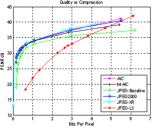
To get a perspective on where that lies, This paper has a number of graphs showing the rapid decline in quality as bits per pixel approaches zero. 
So that's where things stood when I last played with it.  I might be ready to have another go at it. 

Before I dive into it I felt I should write about some of the things that I learned from my previous experience.  Working with the evolver gave me plenty of things to ponder, and I think much of what I have learned came slowly to me during the intervening years as I thought about what it realy means.


Thinking about lossiness and expressiveness 

One of the things my experience helped me with was formalising what is essentialy the obvious idea behind the process of evolving pictures.  The ideal evolvable representation is a dataform which can express the widest range of images while maintaining a similarity between codes with minor differences.   The second aspect of that principle is easy to accommodate, a bitmap does almost exactly this.  A bitmap does a very poor job satisfying the first principle though because the range and difference required has to be considered in the space of everything that humans can perceive.

Here's an example to show the problem.

Spot the Difference.
A and B are one pixel different as are C and D


A single pixel change in the second pair of 64x64 images can be more easily perceived than the first because the image is simpler.   If you are considering each image to occupy a position in the space of human perceivable images you would say the distance between A and B is less than C and D.

The ideal image representation would be something where every codeable image formed evenly spaced points in the full field of humanly perceivable things.    That is ultimately the best that any lossy data compression can achieve.   Finding such a representation is difficult, if not impossible.   Even identifying what is perceivable is a difficult question.  At present, it is even a difficult task to evaluate just how perceptibly different two images are.  Stuctural Similarity (SSIM) is used over Peak Signal to Noise Ratio (PSNR) in many tests.   SSIM is still an extremely crude approximation of what happens during the interaction of the senses and the mind.   To make matters worse, given that our perceptions are also colored by our knowledge, learning more about perception can alter how we perceive things.

Consider this hypothetical idea,  If it were possible to calculate an evenly populated field all perceivable images you could compress any image down to any size with the best possible results.   If you could populate the field with 4 billion evenly spaced points the resulting images could be represented in 32 bits.  Such a compression rate would undoubtedly be extremely lossy, but from a pool of 4 billion distinct images it might get surprisingly close.   This idea is the essence of lossy compression.   Any lossy algorithm aims to produce data that satisfies that criteria.

If you mapped all bit combinations of data of a existing formats you would find points in the field of human perception with uneven spacing and clusters around certain zones.  This is because nobody has yet invented the perfect Image compression algorithm yet.  There is a good reason for that.  We have no idea of what the space of human perception is.  It's probably some many dimensional blob bulging in odd places.  Even if we knew this,  I'm not sure if there would be an accurate way of collecting data on a format short of trying every possible bit pattern.   Hopefully, people way smarter than I are working on these issues.

Even though the ideal is vastly beyond our current reach, it at least can serve as a guide towards what is the right direction.   Changes in data should produce perceivable differences,  but to evolve, small changes should also produce similar images.

In the context of rendering images out of polygons I used irregular hexagons with a bit to encode whether or not to round the edges and a few bits to indicate a blurred edge.  They were easy decisions because looking at other polygon evolvers,  triangles seemed to be insufficiently expressive and images frequently have gradients which are difficult to represent with hard edged objects.

Recently I looked at doing a form of the Image renderer using a GPU shader.   Instead of rendering a polygon and Gaussian blurring it,  my plan was to use distance fields.   When I used hexagons, the evolver managed to do some impressive tricks utilizing self intersecting shapes.  It turns out computing a distance field for a self intersecting hexagon is not as easy as it sounds.  While struggling with the problem, I had a small epiphany.  Two triangles that can combine in multiple ways might be even more expressive.  Here's where I ended up as a base gene.

   red,green,blue,alpha : uint6;
   a1,b1,c1 : {uint8,uint8} //triangle 1 clockwise filled anticlockwise outline.
   a2.b2.c2 : {uint8,uint8} //triangle 2 clockwise filled anticlockwise outline.
   falloff : uint5;
   combineOp : uint3;  // (or, smooth_or, subtract, union...  possibly more )

   Total: 16 bytes;


Here's what the shader can generate from six points.  This returns an alpha value which is combined with the RGBA of the 'gene'.  The combination mode would not be very changeable in a evolving image.  The points should be able to drift freely to make a large number of distinctly different looking shapes.  If the shapes do not intersect at all they take on the appearance of individual triangles.

You can see a version trying various falloff levels on shadertoy

Thinking about Collaborative Image Compression.

When I tried evolving polygon, it was fairly evident that it would not be competitive with compression methods that aim for PSNR values over 30.  The reason was obvious. at that level textures and patterns start becoming apparent which frequency based algorithms can utilize.  Evolved polygons are blissfully unaware of such matters.   This lead me to wonder about mixing methods.

Many a naive coder has had the brilliant idea to try and improve the compression rate of lossless compression by compressing a lossy image and a lossless error map.   After trying a JPEG+PNG  combination they find the combination of the two images is usually more than a PNG on its own.  I have seen a number of people do this, and I did it myself when I was much younger (although I did not use PNG due to it not being invented yet)

That this one way to do it does not work does not invalidate the entire method.  In fact PNG itself does a simple form of this internally.  The main distinction between PNG filters and storing a lossy image as a base is that the filter guesses the next pixel based upon what has already been encoded.  It frequently guesses wrong, but by guessing it doesn't have to store any additional data to make the guess in the first place.   Sometimes this can make things worse if the guesses are consistently wrong.  The corrections might compress less well than the original data would have.  Overall it tends to be a gain.

To take the step of encoding data to provide a base image is a more difficult task.   For every additional byte of data you add to the first stage, you must improve the final stage by more than a byte.  For lossy compression it becomes more unclear,  for every byte spent, you must gain more than a byte's 'worth'.   Since we are aiming for quality, the question is more to do with whether or not spending the byte early or spending it later results in the best image.

You may now see why this idea became of interest to me again after experimenting with the evolved images.    The broad strokes approach of the polygon renderer exhibits the sort of profile we would look for in a first stage.  It exhibits the most rapid gains towards the target image at the lowest bit-per-pixel rates.

The area that I would really like to explore is the idea of eliminating the concept of a first pass followed by a correction pass,  but to see if a dynamically collaborative process could be obtained.    Have a modular compression system where a compression algorithm module receives a working-image and an allocation of bytes and it tried to spend its bytes on encoding a modification to the working-image to better match the goal image.

The polygon evolver approach roughly resembles this mechanism already.  Each polygon is encoded into a number of bytes and is rendered on top of the existing image.   Polygons exist as 16 byte packets.  Adding a polygon (after evolution) results in a net gain in image quality.  

Extending this principle to multiple encoding methods has advantages and disadvantages. The advantages are obvious, using multiple techniques permits specialization . Specialization means the best performing technique can be chosen for image components. The main disadvantage is that specialization requires extra data to encode what method is chosen and where in the image that data applies.

In normal image compression some of the required information is implied by the format or context.  DCT compressed images like JPEG store blocks as (usually) 8x8 cells.  The same image could be encoded in a multi-algorithm image if it had a DCT module that handled a cell per data packet.  The resulting image would look the same but have a larger data size.  Every packet would have to encode data to say "This is a DCT cell at position x,y".   JPEG gets that data for free.  It's DCT because that's what JPEG does, and the position is "right after the last cell we decoded".

You could potentially squeeze that extra data into a small space, a data packet beginning  single zero bit could indicate a the same type as the previous.  Similarly if a DCT packet began with a zero it could indicate that it comes right after the previous cell in the picture.  That would mean our hypothetical all-DCT image might only gain an additional 2 bits per cell.   You wouldn't do that of course.  Enabling multiple encoding techniques then using a single one eliminates all of the advantages of the system.

Where this idea would work best is for mixing a few techniques together.  You may only end up with 5 DCT blocks in an image strategically placed in places where the polygonal method fails the worst.  Or perhaps a glyph encoder is a better solution where it encodes on the assumption that it is encoding a bi-level or alpha-mask image where set pixels are usually by other set pixels and clear pixels are usually by other clear pixels.

Generating images using all these methods together is an interesting challenge. but I think it might be doable. 


Before I dive into that part, I should first make a WebGL polygon shader evolver using my triangle pairs approach to hee how well it works.


Friday, January 1, 2016

A Little Calculator.

I'm trying out Cinnamon. It seems to be quite a nice environment, but I couldn't find a Calcuator that met my needs. This was the Calculator I found.
For me, it was too large and inflexible. I wanted something where I could type in complex expressions and easily do so while referring to the contents of another window.

My criteria were:
  • Small: So it does not obscure the information I am referring to for the calculation
  • Stay-on-top: So that when I click on a window to type in the result of the calculation, the calculator doesn't disappear
  • Draggable: So if it is in the way it can readily moved to another spot
  • Easy to summon and dismiss
  • Expressions can be typed in directly
  • Support for Hex and Binary
  • Recallable history
I have used a little Calculator on my Windows machine for years that has all of these properties. I couldn't find what I wanted there either, so I knocked together something in Delphi. It has been an extremely useful little thing that has come in handy for many years now (the .exe I still use has a creation date of 2003) . So I've only been using Cinnamon a couple of months now and I'm quite new to using Clutter, but here's what I have managed so far.
It's on GitHub

Tuesday, October 13, 2015

Hex Cellular Automata

I have a project that could use a massive field of fluid as a base. To do this I'm going to need to be able to do a decent speed fluid simulation, This is my first attempt at doing any sort of fluid at all. My previous post shows the various states that the cells can have. I managed to cobble together a decent JavaScript implementation.

This implements a 350x250 hex grid, The actual field size that I want to have will be much larger and will require GPU accelleration.

Thursday, October 8, 2015

Symmetry

I'm making a Cellular Automata on a hex grid. Before I actually write the code for the cells I had to write this visualisation to ensure I got the rules correct, The same rule should apply for all cells of the same structure regardless of orientation, so all rotations and flips get the same rule.

After writing this I'm fairly certain I would have screwed up the rules without it. Trying to detect mistakes from the behaviour of the rules would be nearly impossible I think.. Mouse over cells to see the matches.


Wednesday, September 30, 2015

Charged Particles

I wrote this little program while I waited for some SDKs to download. It's just a toy to play with the dynamics of charged particles. While not directly accurate to any real world physical model (not least because it is only 2D), it can demonstrate some principles of chemistry. The principles of molecules and chemical reactions can be seen as charged particles attract, assemble and react to the presence of new charges.


Left, Middle, and Right mouse buttons place particles of -1, random, +1 respectively

Use number keys 1-9 & 0 to place particles in a range of -1 to +1